From chat window to my desk: An AI-designed split keyboard
Building an RP2040 Corne and printable enclosure with AI, TypeScript, and tscircuit.
I wanted to find out if I could turn a conversation with AI into a working keyboard. I started with Foostan’s Corne and asked AI to copy over the PCB dimensions and placement of keys and then design a printable enclosure for it all in tscircuit.
I ended up with a working RP2040 split keyboard with Choc switches, USB-C, a TRRS connection between the halves, and a matching enclosure. My job was to describe what I wanted, check the previews, and ask for changes until the fit looked right. AI wrote and revised the code.
In tscircuit, the design is written in TypeScript and JSX. Each key is a reusable component, with props for its position and rotation. The connections are written in code too. Here’s a small example from the project:
<ChocKey
  name={component.name}
  pcbX={component.pcbX}
  pcbY={component.pcbY}
  pcbRotation={-(component.pcbRotation ?? 0)}
/>
<trace from=".SW1 > .pin1" to=".U1 > .pin14" />
The ChocKey component combines the imported hot-swap socket footprint with the switch’s mechanical geometry. Removable switches are marked doNotPlace so they can be fitted separately from factory assembly.
Routing without the long wait
Once the components and connections were in place, tscircuit’s autorouter handled the copper routes and vias for both halves. Routing this board in tscircuit was quick. I gave Astra a try and then lost my patience cause it took more than 3hrs and it still was going on. Being able to reroute quickly by the tscircuit autorotuer made it easier to try changes and check the results.
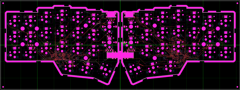
The panel layout in tscircuit’s PCB viewer, with both keyboard halves side by side.
The manufacturing limits are in the same code:
<board
  outline={outline}
  minTraceToHoleEdgeClearance={0.21}
  minViaHoleDiameter={0.2}
  minViaPadDiameter={0.45}
>
  {layout.components.map(renderComponent)}
</board>
For the enclosure, I asked AI for a flat case, thin walls, a switch plate, and supports to reduce flex. It uses the PCB’s outline, mounting holes, and key positions, so everything shares the same coordinates. I could check how the PCB and enclosure fit together in tsci dev before sending the board for fabrication:
import { assembly } from "tscircuit"

<assembly.device name="CORNE_LEFT">
  <CorneHalf side="left" />
  <CorneEnclosureParts side="left" />
</assembly.device>
Inside that wrapper, the case and plate are assembly.printedpart elements with generated CAD geometry. The base and plate export as separate STEP files for slicing and 3D printing.
For CAD work, the CLI can also export the enclosure’s printed parts together as a STEP assembly. For the left half:
tsci export left.circuit.tsx \
  --format assembly-step \
  --output corne-left-enclosure.step
The assembly-step format preserves the printed parts as separate named parts in one assembly. Use --format step for a STEP export of the PCB and its electronic components.
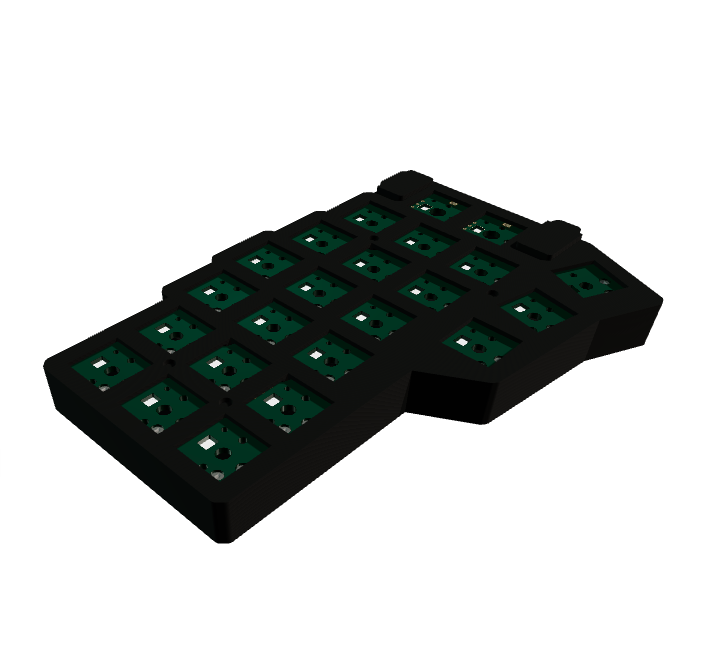
The PCB and black enclosure previewed together in tscircuit’s 3D viewer.
When something needed changing, I could just ask: “make the plate flat,” “use the existing mounting holes,” or “leave room for the cable.” Then I’d check the updated preview before ordering or printing anything.
I brought the exported STEP files into Bambu Studio to prepare the case and switch plate for 3D printing.
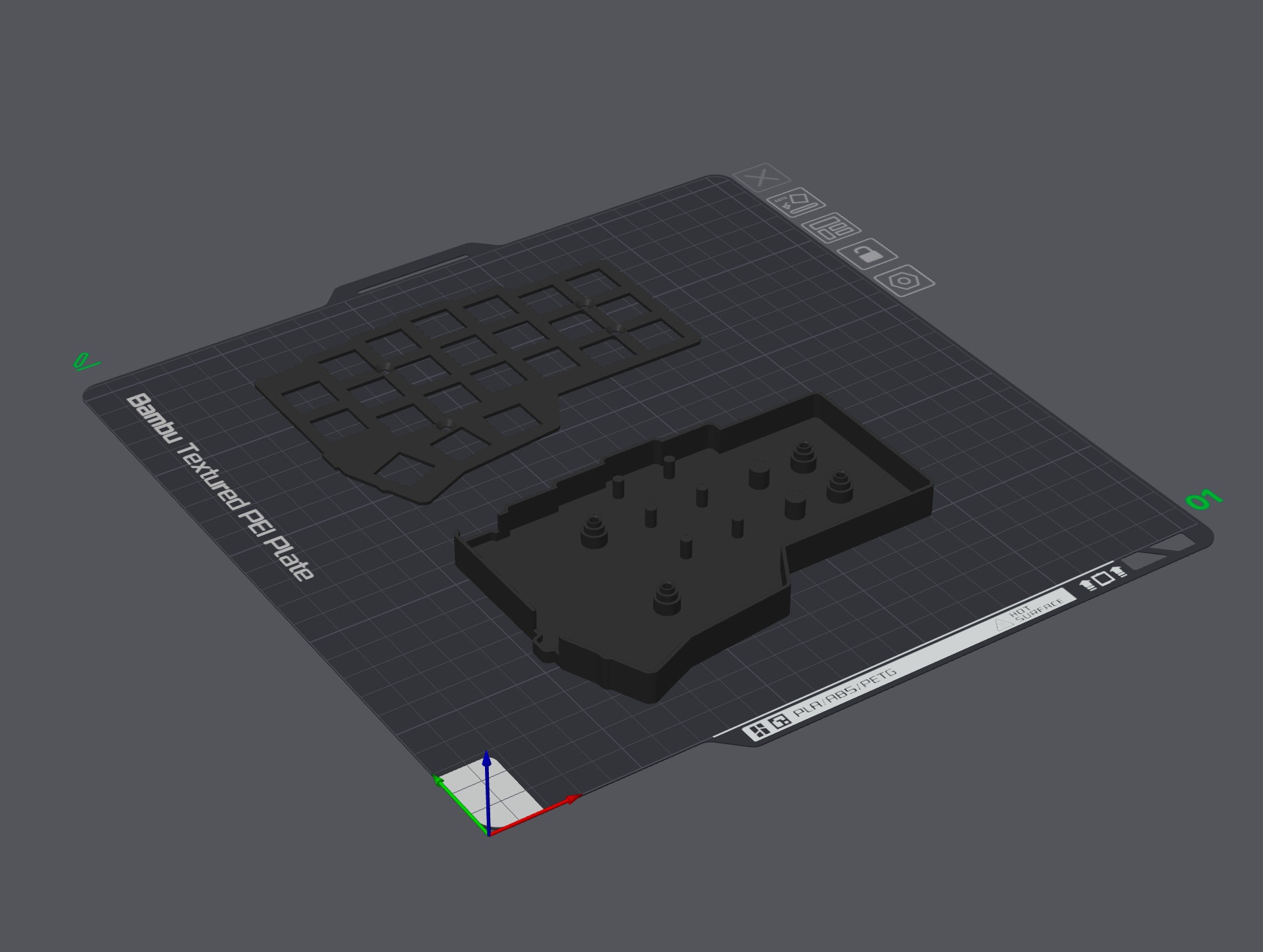
The case and switch plate in Bambu Studio, ready for printing.
Before fabrication, I also reviewed the panel containing both keyboard halves in tscircuit’s 3D viewer.
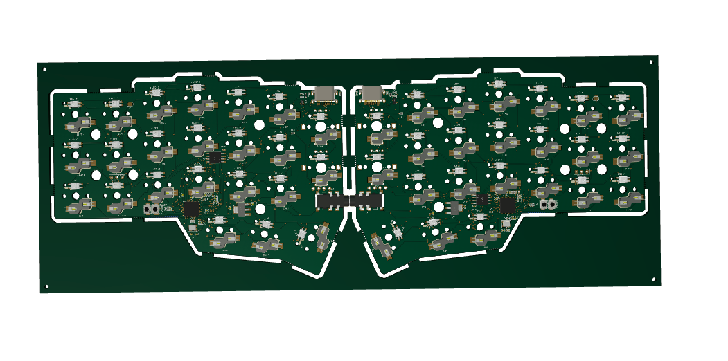
The 3D panel preview rendered in tscircuit before fabrication.
From fabrication to the first firmware test
Once I was happy with the design, I sent PCBWay the Gerbers and drill files, a grouped BOM, and the pick-and-place file for a panel containing both halves. The fabrication files went into a ZIP:
tsci export panel.circuit.json --format gerbers --output corne-fabrication.zip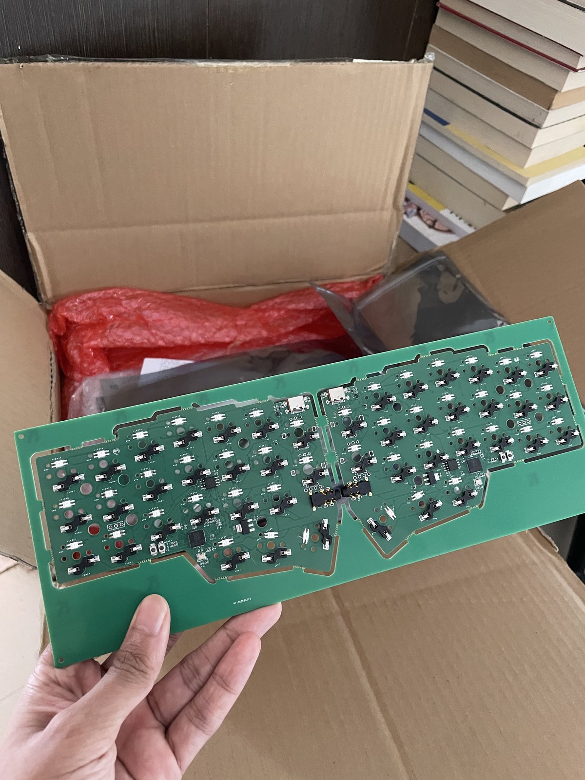
The panel PCBWay sent, containing both keyboard halves.
AI generated the firmware too. Flashing both halves was just drag and drop: I plugged each half in over USB in bootloader mode and dragged its firmware file onto the drive that appeared. Once both were flashed, I connected them for the first test.
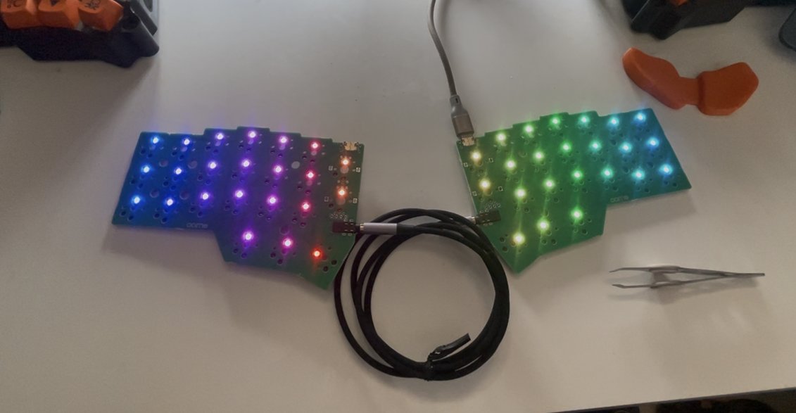
The first test after flashing the AI-generated firmware, with the LEDs glowing on both halves.
The finished keyboard
Once the firmware was running, I fitted the switches and keycaps and put both halves in their black printed cases. There it was: a working keyboard on my desk.
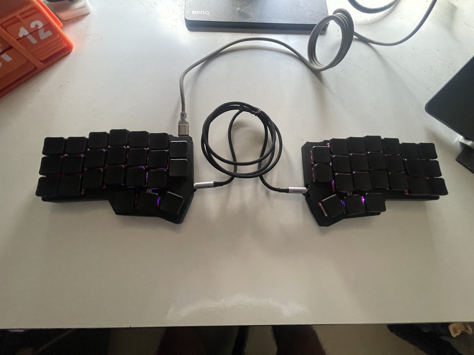
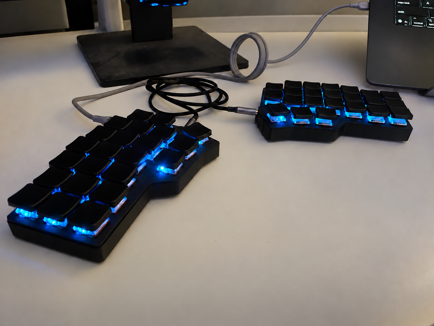
Another look at the finished keyboard, with the blue backlighting on.
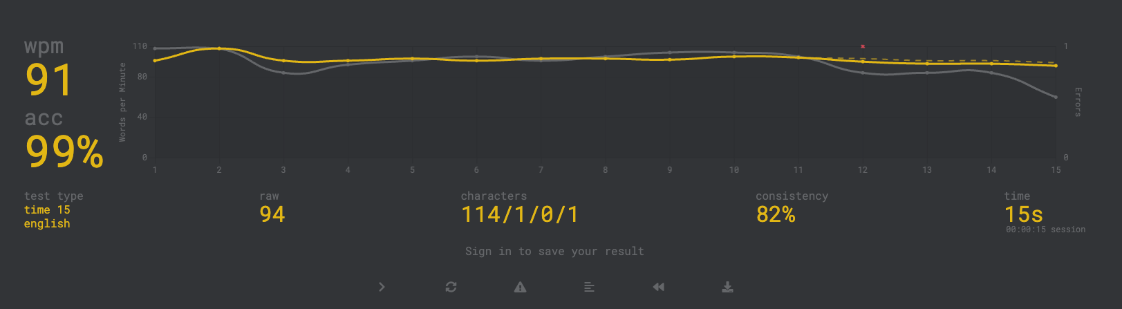
A quick typing test
91 WPM with 99% accuracy. The keyboard works; still a bit away from my best score. 😅

Crazy times ahead where you can prompt a product to reality without knowing single line of code or being a hardware expert. Go checkout tscircuit.com